Automating my Fantech HRV with Modbus
Ventilation in my home is handled by a Fantech Hero 120H heat-recovery ventilator (HRV), managed by a Fantech EDF-8 wall controller. An HRV exchanges stale indoor air for fresh outdoor air while transferring heat between the two streams, so you get ventilation without throwing away all the energy spent heating or cooling your home.
I wanted my HRV integrated into Home Assistant so that ventilation tracks humidity, occupancy, and air quality, rather than sitting at whatever fixed speed I last picked on the wall.
To automate this I used:
A Seeed Studio Xiao ESP32-C6 (other ESP32 boards work too)
An RS-485 to UART transceiver module
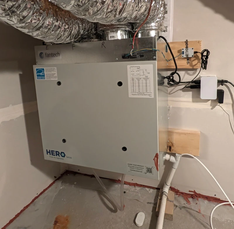
The final result, the HRV controller is in the top right of the image.
I took the hard path and reverse engineered the protocol between the EDF-8 and the HRV; that’s documented below for anyone who wants to use the interface. The reverse engineering effort turned out to be unnecessary, because the Hero 120H also speaks Modbus, and that’s what I actually used.
Reverse engineering the two-wire controller
Before I attempted the easier path (next section), I reverse engineered my two-wire controller. I put a scope on the two controller wires, probe on the white wire and ground on the black, and captured the bus in every controller state: each fan speed, each air source, off, periodic mode, and auto mode with a humidity setpoint.
Physical layer
The controller uses only two wires, data to/from the HRV and power from the HRV share the same pair.
The manual says the two wires do not have polarity.
I assume there is a bridge rectifier in the controller.
The bus idles high at 14.3 V with 1.4 V peak-to-peak ripple.
I assume there is a reservoir capacitor to ride through the brief lows during data TX/RX.
The two transmitters produce two different swings:
HRV: high ~14.3 V, low ~0 V.
Controller: high ~11 V, low ~3 V.
Exact values likely depend on the resistance between the HRV and controller.
Link layer
Plain UART.
1200 baud
8N1
Non-inverted: idle high, low start bit
Data bits LSB first
No parity
Bus traffic
The HRV is the bus master and polls the controller about once per second (1020 ± 5 ms). Each cycle is two transmissions:
Poll: the HRV sends a single byte,
0x2A(*).Response: the controller answers with a 6-byte ASCII frame,
$C<air><fan>H>.
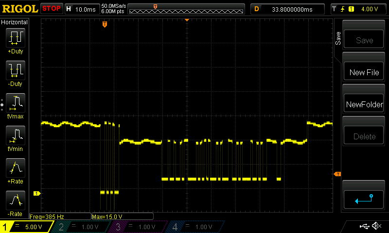
Oscilloscope capture of a single poll/response cycle.
The response frame is the controller telling the HRV its current selection:
Byte |
Value |
Meaning |
|---|---|---|
0 |
|
start delimiter |
1 |
|
constant in every capture, purpose unknown |
2 |
|
air source: External, Recirculate, Standby (off) |
3 |
|
fan speed: Low, Medium, High |
4 |
|
constant in every capture, purpose unknown |
5 |
|
end delimiter |
For example, medium fan with external air is $CEMH>, and off is $CS?H> with the fan byte retaining its previous value.
Pressing buttons on the controller produces no extra traffic. The 1 Hz response is the command channel.
Other controller features
The captures when the controller is in periodic mode (20 minutes per hour) and hygrostat mode (humidity control) are byte-for-byte identical to the corresponding manual-speed captures.
The controller resolves its mode and setpoint locally and transmits only the resolved air source and fan speed.
I didn’t end up using the two wire bus because it’s bespoke, and there was an easier path.
Bypassing the controller with Modbus
Although my EDF-8 is a two-wire controller, the Hero 120H manual documents a priority order for all of its control inputs:
Remote Off (S+/S-)
Timer (T+/T-)
Defrost Cycle (internal)
Dehumidistat (D+/D-)
Four-wire controller (B/A)
Two-wire controller (W/W)
Speed selection switch
The list is ordered by precedence, and my EDF-8 sits near the bottom of it. Above my EDF-8 is the “four-wire controller” on terminals B/A, and B/A is the classic naming for the two lines of an RS-485 differential pair.
Dustin Thomson had a similar Fantech Hero HRV with a Modbus controller, reverse engineered its RS-485 interface, and documented the Modbus registers.
I had no confirmation that this would work on my Hero 120H, so I blindly tried Modbus.
I wired an ESP32-C6 and an RS-485 transceiver to the B/A terminals and queried register 0x3E; it worked, and the register map from Dustin’s post applied to my unit as-is.
Hardware
The ESP32-C6’s UART pins connect to the RS-485 to UART transceiver, and the board’s A/B/G outputs connect to the HRV’s B/A/G terminals.
ESP32-C6 Pin |
RS-485 to UART transceiver |
|---|---|
3.3V |
VCC |
GND |
GND |
GPIO16 |
TXD |
GPIO17 |
RXD |
RS-485 to UART transceiver |
HRV |
|---|---|
A+ |
A |
B- |
B |
GND |
G |
Case
Inspired by Guo-Rong’s case design for the pico-cec project (see Automating TV power with HDMI-CEC), I built a 3-piece design:
A lid.
A middle tray for the Xiao ESP32-C6.
A bottom tray for the RS-485 to UART transceiver module.
I took an off-the-shelf 3D model for the Xiao ESP32-C6, and had Sonnet create an OpenSCAD model of the RS-485 module from my measurements.
I used OpenSCAD because it creates 3D models from code, which makes it easy for LLMs to use.
I gave Sonnet instructions on how to render .scad files to images and set it to work adapting the pico-cec design for this project.
This took many iterations; Sonnet’s vision capabilities still can’t tell when something is parallel or perpendicular.
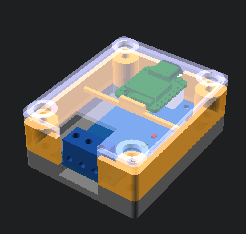
Transparent render of the case.
The assembly is straightforward: 4 hookup wires soldered between the two boards, with 4 × 20 mm M3 screws and nuts to hold everything together.
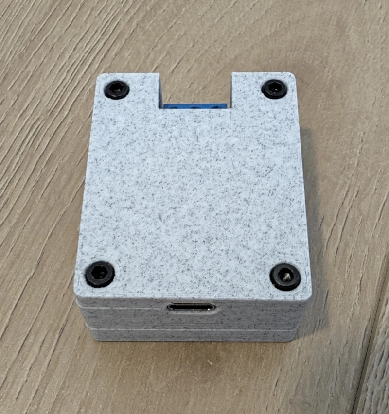
Assembled controller.
I used the first iteration of this case I printed, but there are some things I would change if I printed another:
The screw holes were too small, I had to drive the screws into the plastic itself.
The ESP32-C6 tray had too much extra space at the back.
All design files for the case are on GitHub: newAM/fantech-hrv-esp32c6
Mounting
I mounted the assembly next to the HRV with some metal strapping that was lying around.
The final result, the HRV controller is in the top right of the image.
Firmware
I adapted Dustin Thomson’s ESPHome configuration with some changes:
Added API encryption.
Added an
"Unset"option mapped to register value 0.0x3Ereads 0 until it has been written over Modbus at least once.
Changed board specific configuration to match my Xiao ESP32C6.
Changed the select mode to
optimistic. The UI updates immediately on write instead of waiting for the next poll.Fixed compiler warnings.
The full ESPHome configuration is on GitHub: hrv.yaml
Home Assistant
Home Assistant auto discovered the new ESPHome device.
There are only two useful entities that I put on my dashboard: the intake temperature, and the HRV mode.
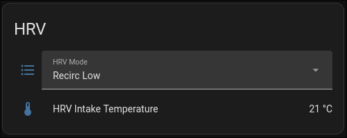
HRV card in Home Assistant.
The most useful automation I have created turns on HRV ventilation when carbon dioxide levels exceed 800 ppm. For why that threshold matters, see Mike Bowler’s excellent piece on carbon dioxide: The bottleneck might be the air in the room
What happened to the wall controller
The EDF-8 is still on the wall, and as long as I only read registers over RS-485 it works as before: it keeps answering the HRV’s polls, state changes made on the controller still reach the HRV, and its display stays accurate.
The first write over Modbus changes the relationship. After setting the state via Modbus the original controller does nothing:
State changes made on the controller no longer apply to the HRV.
The controller’s display becomes inaccurate: changes made over RS-485 do not update the display, it shows the controller’s last selection rather than what the HRV is actually doing.